
-
Low-Temperature Testing
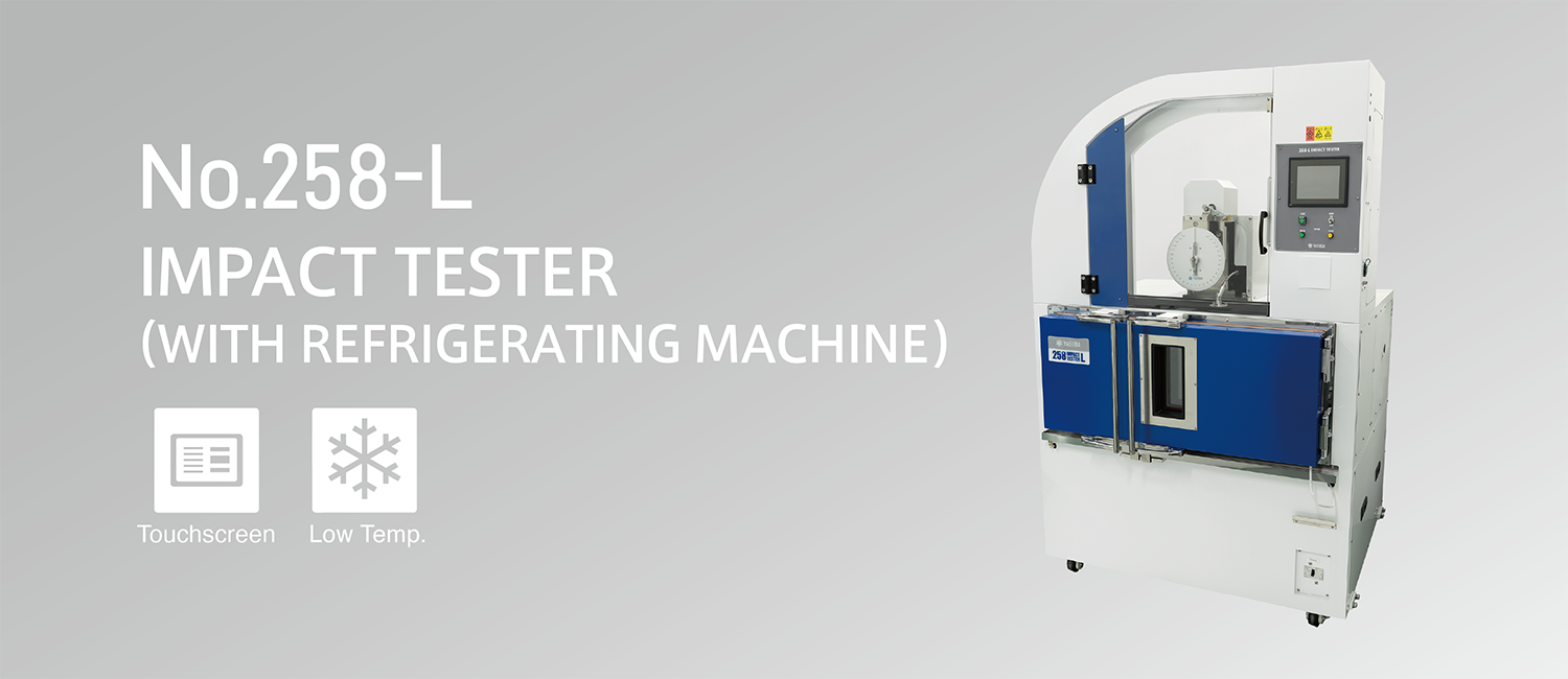
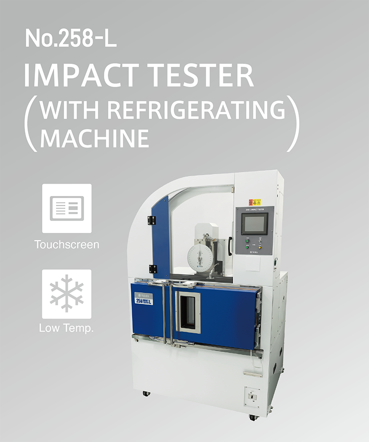
Two Types of Low-Temperature Impact TestersImpact testing can also be performed in low-temperature environments. The No.258-L allows testing between -35℃ to 60℃, while the No.258-UTL supports testing as low as-50℃ to 60℃. Please select the model that suits your desired testing temperature.
-
Touchscreen Operation
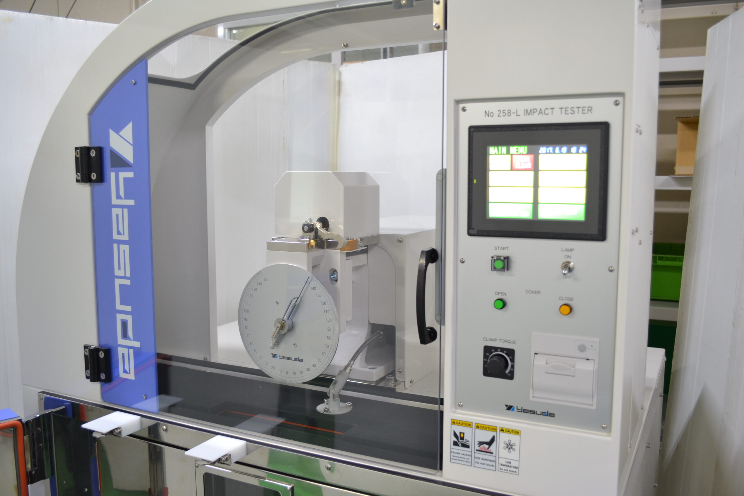
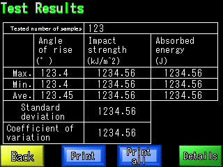
Basic Operation and Result Registration AvailableBasic operations are performed using the touchscreen. After the test, the impact value is automatically calculated based on the hammer lift-up angle.
The test results can also be checked in the test results screen. -
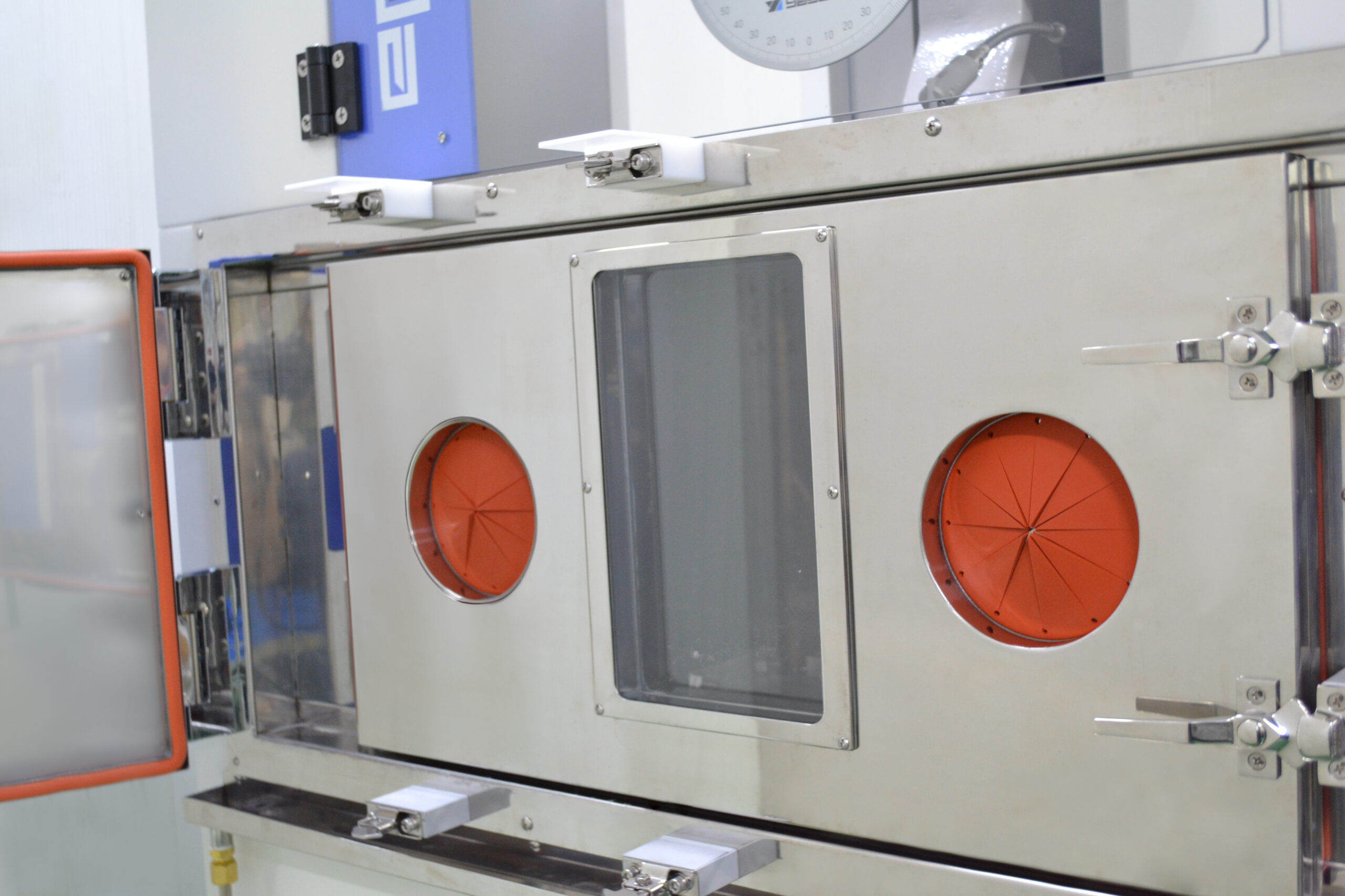
Accurate Testing
Testing Inside the Low-Temperature ChamberImpact testing is performed inside the low-temperature chamber, ensuring accurate testing conditions without any change in the test environment. Testing inside the chamber also prevents sample scatter, making sample collection easier.
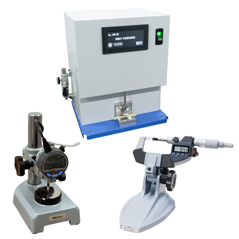
Input Tools for Increased Efficiency
We offer three types of input tools that simplify sample dimension measurement. These tools significantly reduce measurement time and improve testing efficiency.
| Temperature | -35℃–60℃ (refrigeration control) |
|---|---|
| Main Unit Specifications | ・Touchscreen operation ・Analog Scale included ・Electric hammer release ・Safety cover with interlock |
| Safety Devices | Safety cover with interlock switches |
| Other specs | Refer to the specifications of No.258-D/PC |
| Power Source | AC 200 V 3-phase 40 A 50/60 Hz |
| Dimensions and Weight(Approx.) | W1,100×D1,160×H1,760 mm, 450 kg |
Common Specifications
| Standards | JIS/ISO | ASTM | |||
|---|---|---|---|---|---|
| Reference Standards | JIS K 7111-1,ISO 179-1 | JIS K 7110,ISO 180 | ASTM D6110-10 | ASTM D256 | |
| Test Method | Charpy Impact Test | Izod Impact Test | Charpy Impact Test | Izod Impact Test | |
| Hammer Energy Capacity (J)*1 | 0.5, 1, 2, 4, 5 | 7.5, 15, 25*2 | 1, 2.75, 5.5, 11, 22 | 2.7 and above (past results: 0.5, 1, 2, 4, 5, 7.5, 15, 25) | 2.7 to 21.7 (past results: 1, 2.75, 5.5, 11, 22) |
| Anvil Lift for Charpy | Required | – | – | – | – |
| Impact Velocity | 2.9m/s | 3.8m/s | 3.5m/s | 3.46m/s | 3.5m/s |
| Hammer Release Angle | 150° | ||||
| Hammer | Refer to the respective sections below for details. | ||||
| Anvil | Refer to the respective sections below for details. | ||||
Hammer
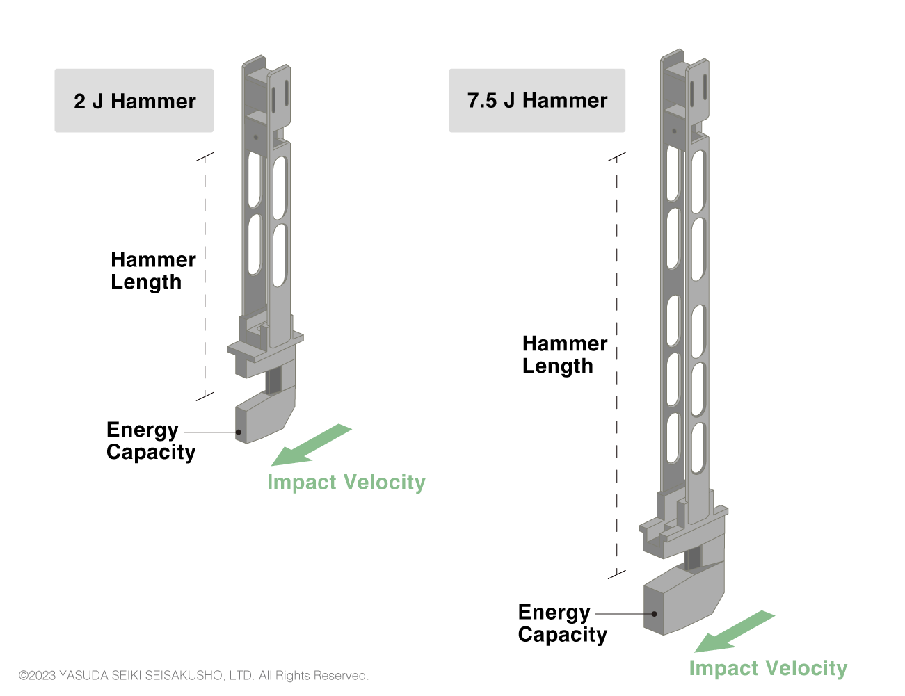
| Standard | Potential Energy | Impact Velocity | Angle of Striking Edge | Radius of Striking Edge |
|---|---|---|---|---|
| ISO/ JIS |
0.5J | 2.9m/s | 30±1° | R2±0.5mm |
| 1J | ||||
| 2J | ||||
| 4J | ||||
| 5J | ||||
| 7.5J | 3.8m/s | |||
| 15J | ||||
| 25J | ||||
| ASTM | 2.7 and above (past results: 0.5, 1, 2, 4, 5, 7.5, 15, 25) | 3.46m/s | 45±2° | R3.17±0.12mm |
The characteristics of the Charpy hammers differ between the test standards as shown in the table above. In ISO and JIS standards, the hammer length changes according to the impact velocity. Therefore, the same hammer cannot be used to create, for example, a 4 J impact and 7.5 J impact. Two different hammers must be prepared.
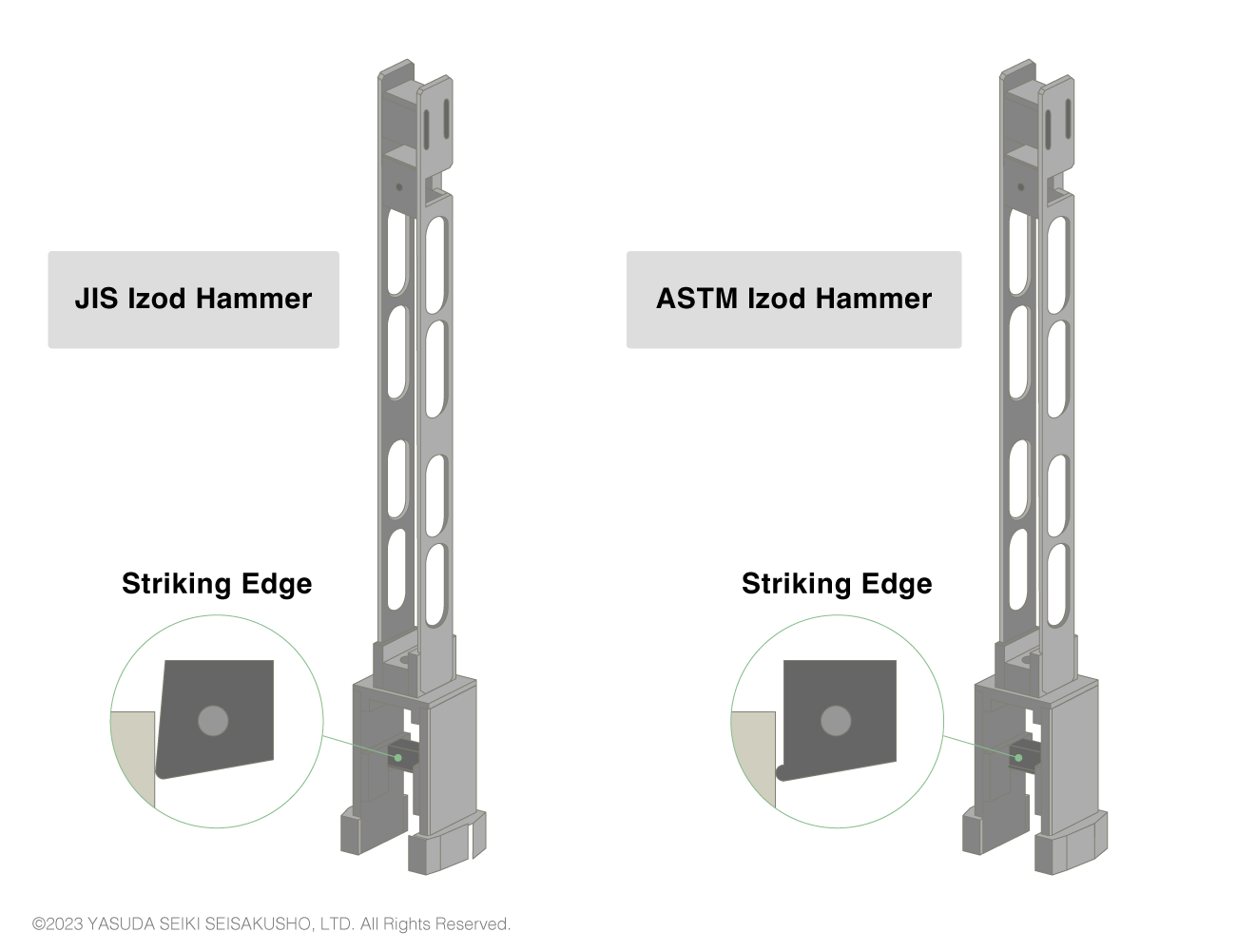
| Standard | Potential Energy | Impact Velocity | Radius of Striking Edge |
|---|---|---|---|
| ISO/ JIS |
1J | 3.5m/s | R0.8±0.2mm |
| 2.75J | |||
| 5.5J | |||
| 11J | |||
| 22J | |||
| ASTM | 2.7-21.7J | 3.5m/s | R0.8±0.2mm |
The same hammer is sometimes used between ISO (or JIS) and ASTM impact tests as the details of the hammers specified in the two standards are similar. However, to be precise, the shape of the striking edge differs between the standards as shown in the above image. Therefore, to conform to the test standards, hammers that match the test standard shall be used.
Anvil
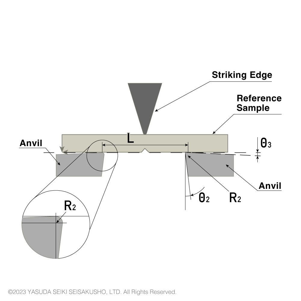
| Symbol | Parameter | ISO/JIS | ASTM |
|---|---|---|---|
| ー | Parallelism between long axis of test sample and reference plane | ±4/1000 | ー |
| R2 | Radius of curvature of anvils | 1±0.1 mm | 3.17±0.12 mm |
| θ2 | Angle of taper of anvils | 10±1 ° | 0 |
| θ3 | Angle of slope of anvils | 5±1 ° | 0 |
| ー | Angle of supports and anvils | 90±0.1 ° | 90° |
| L | Span between sample supports | 62±(0.5/0) mm | 101.6±0.5 mm |
The shape of the anvil differs between ISO (or JIS) and ASTM standards. Therefore, to perform both ISO and ASTM standardized tests, two different anvils shall be prepared.
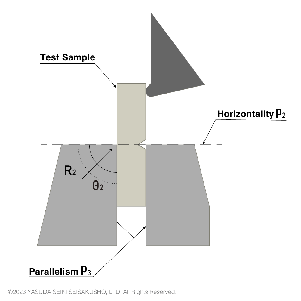
| Symbol | Parameter | ISO/JIS | ASTM |
|---|---|---|---|
| ー | Sample angle | 90±2 ° | ー |
| ー | Parallelism with face of reference sample | ±0.025 mm | ー |
| P2 | Horizontality of top surface of vise | ±3/1000 | ー |
| θ2 | Angle between support block and top surface of vise | 90±0.5 ° | ー |
| P3 | Parallelism in horizontal and vertical direction | ±0.05 mm | ー |
| R2 | Top edge radius of support | 0.2±0.1 mm | 0.25±0.12 mm |
In strict terms the anvil shapes differ between ISO (JIS) and ASTM standards, but are sometimes used mutually as the differences are minor.
Send measured dimensions to the main unit at the press of a button, reducing the time and effort required to input dimensions manually.
*Compatible with No.258-D and No.258-L.
Add weights to the hammer to support two capacities.
By pressing a button, the hammer can be stopped with the brake engaged. This ensures safe hammer stoppage after impact without the risk of hand contact.
* Available for Izod only.
Contact Us
For over 70 years, Yasuda Seiki’s testing machines have supported quality control and research & development across various industries, meeting the diverse needs of our clients.