
Operation Video
-
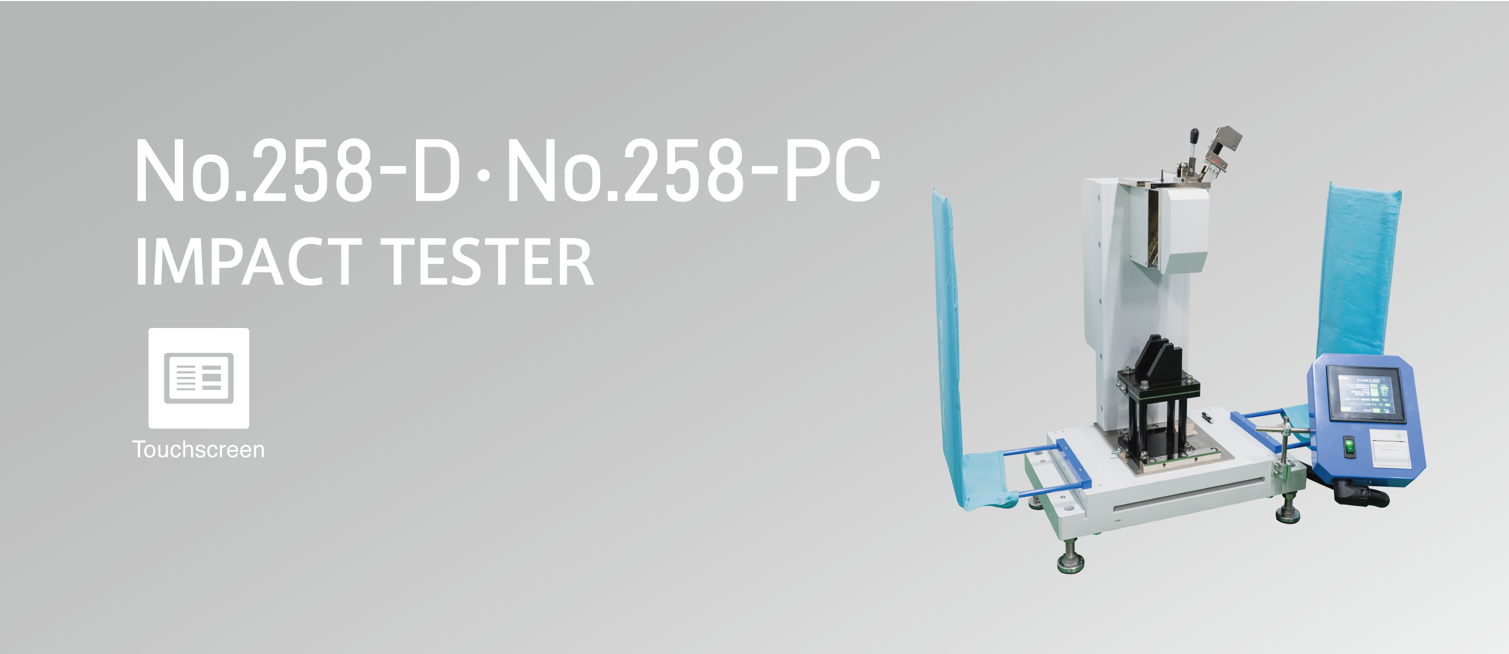
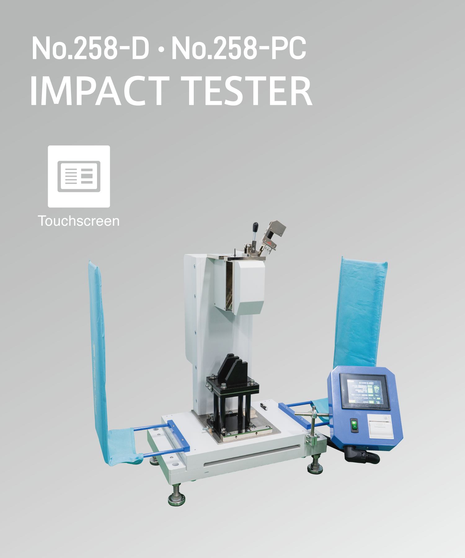
Simplest and Easily Operated
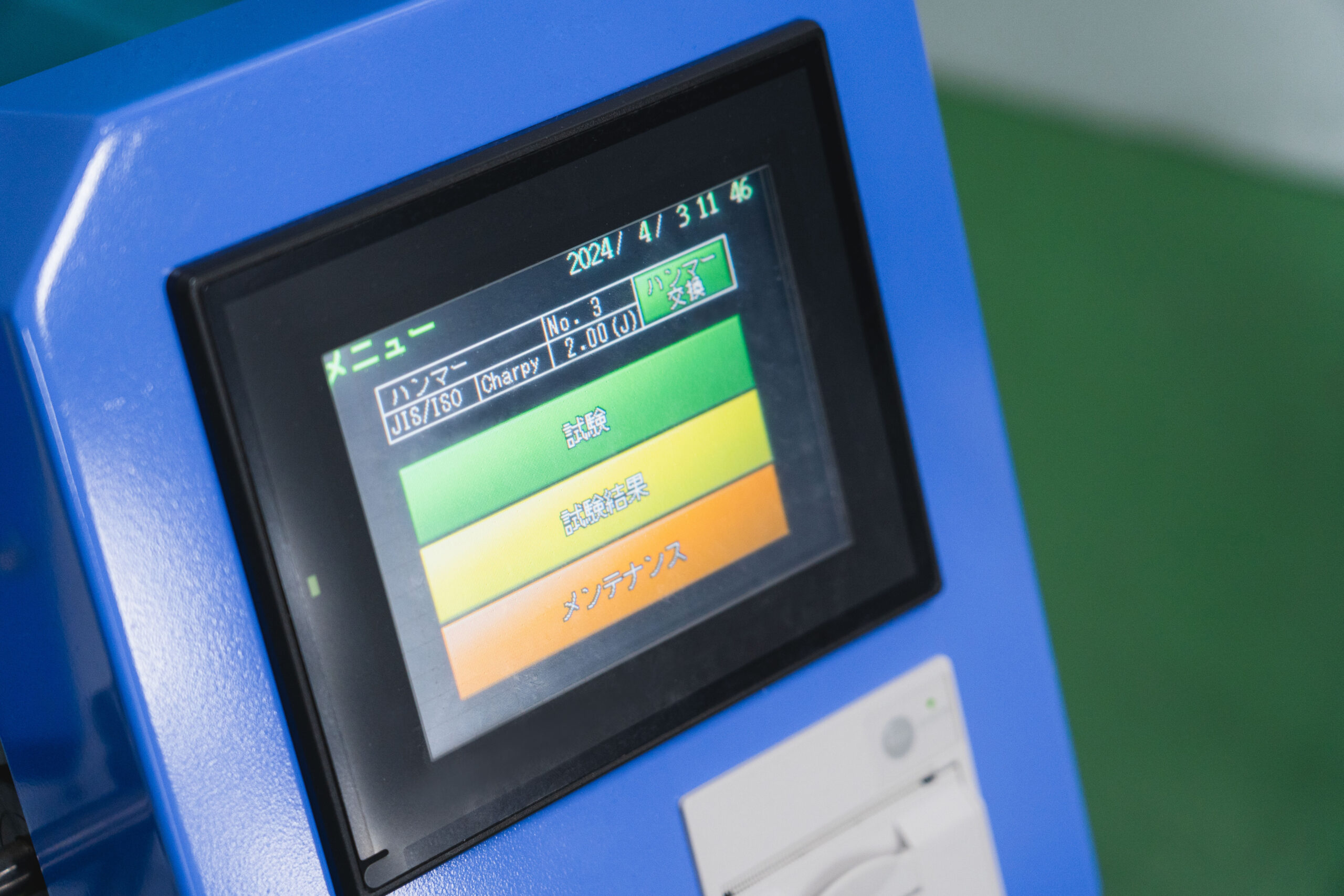
Smooth Testing ExperienceThe lift-up angle of the hammer after impact is automatically measured, and the impact energy is calculated. Operation methods can be selected from touchscreen control (Model No.258-D) or PC control (Model No.258-PC).
The No.258-D model was updated with new software in 2024, significantly improving operability and user experience. -
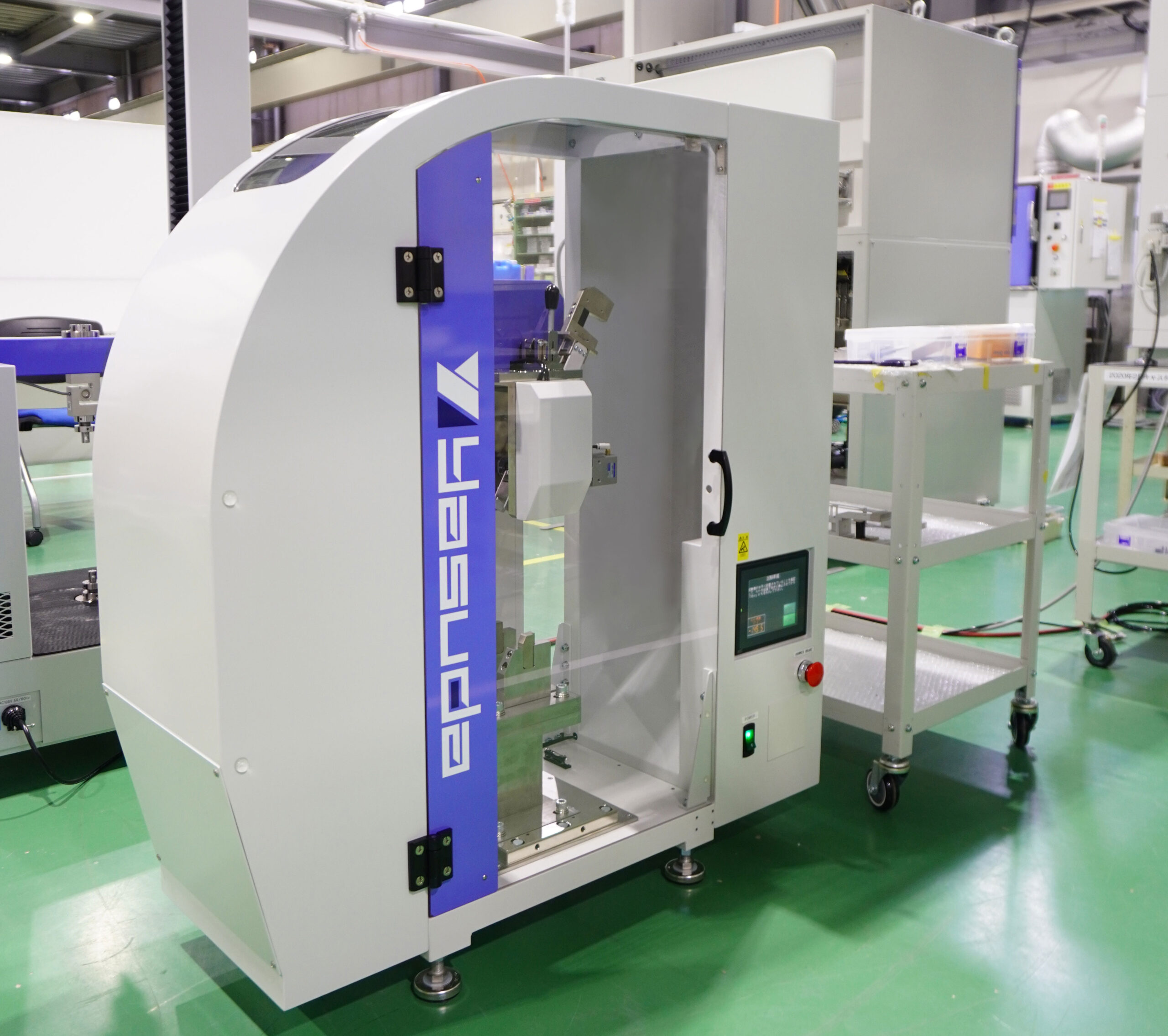
Safety Cover Specifications
Full-Cover SpecificationThe testing area can be completely enclosed with a safety cover, ensuring both the hammer does not come into contact with the operator and preventing test sample scatter. Hammer release and other operations can be performed via the touchscreen.
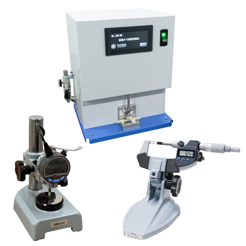
Input Tools for Increased Efficiency
We offer three types of input tools that simplify sample dimension measurement. These tools significantly reduce measurement time and improve testing efficiency.
| Operation Method | No.258-D: Touchscreen Operation No.258-PC: PC Operation |
|---|---|
| Dimensions (Approx.) | 258-D: W500 (+W520 mm with side guards)×D650×H880 mm, 258-PC: W500 (+W520 mm with side guards)×D530×H880 mm, Safety cover (full cover) specification: W1,000×D550×H1,120 mm |
| Weight (Approx.) | 258-D/PC: 150 kg (+5 kg with side guards) , Safety cover (full cover) specification: 180 kg |
| Power Source | AC 100 V 1-phase 3 A 50/60 Hz, Safety cover (full cover) specification: AC 100 V 5 A 50/60 Hz |
| Standard accessories | Tools and equipments for basic installation(includes anvil, hammer level checking tool, sample centering tool*, hex keys, etc.) |
Common Specifications
| Standards | JIS/ISO | ASTM | |||
|---|---|---|---|---|---|
| Reference Standards | JIS K 7111-1,ISO 179-1 | JIS K 7110,ISO 180 | ASTM D6110-10 | ASTM D256 | |
| Test Method | Charpy Impact Test | Izod Impact Test | Charpy Impact Test | Izod Impact Test | |
| Hammer Energy Capacity (J)*1 | 0.5, 1, 2, 4, 5 | 7.5, 15, 25*2 | 1, 2.75, 5.5, 11, 22 | 2.7 and above (past results: 0.5, 1, 2, 4, 5, 7.5, 15, 25) | 2.7 to 21.7 (past results: 1, 2.75, 5.5, 11, 22) |
| Anvil Lift for Charpy | Required | – | – | – | – |
| Impact Velocity | 2.9m/s | 3.8m/s | 3.5m/s | 3.46m/s | 3.5m/s |
| Hammer Release Angle | 150° | ||||
| Hammer | Refer to the respective sections below for details. | ||||
| Anvil | Refer to the respective sections below for details. | ||||
Hammer
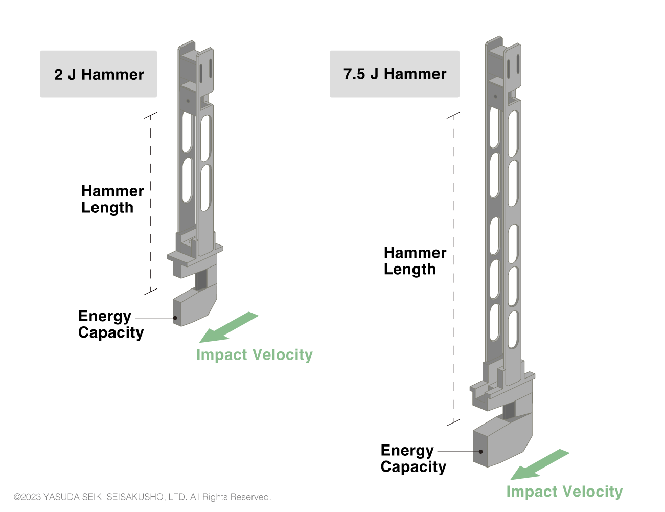
| Standard | Potential Energy | Impact Velocity | Angle of Striking Edge | Radius of Striking Edge |
|---|---|---|---|---|
| ISO/ JIS |
0.5J | 2.9m/s | 30±1° | R2±0.5mm |
| 1J | ||||
| 2J | ||||
| 4J | ||||
| 5J | ||||
| 7.5J | 3.8m/s | |||
| 15J | ||||
| 25J | ||||
| ASTM | 2.7 and above (past results: 0.5, 1, 2, 4, 5, 7.5, 15, 25) | 3.46m/s | 45±2° | R3.17±0.12mm |
The characteristics of the Charpy hammers differ between the test standards as shown in the table above. In ISO and JIS standards, the hammer length changes according to the impact velocity. Therefore, the same hammer cannot be used to create, for example, a 4 J impact and 7.5 J impact. Two different hammers must be prepared.
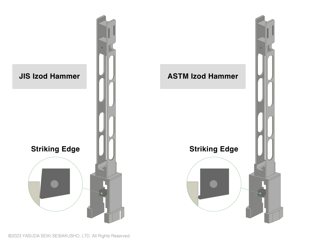
| Standard | Potential Energy | Impact Velocity | Radius of Striking Edge |
|---|---|---|---|
| ISO/ JIS |
1J | 3.5m/s | R0.8±0.2mm |
| 2.75J | |||
| 5.5J | |||
| 11J | |||
| 22J | |||
| ASTM | 2.7-21.7J | 3.5m/s | R0.8±0.2mm |
The same hammer is sometimes used between ISO (or JIS) and ASTM impact tests as the details of the hammers specified in the two standards are similar. However, to be precise, the shape of the striking edge differs between the standards as shown in the above image. Therefore, to conform to the test standards, hammers that match the test standard shall be used.
Anvil
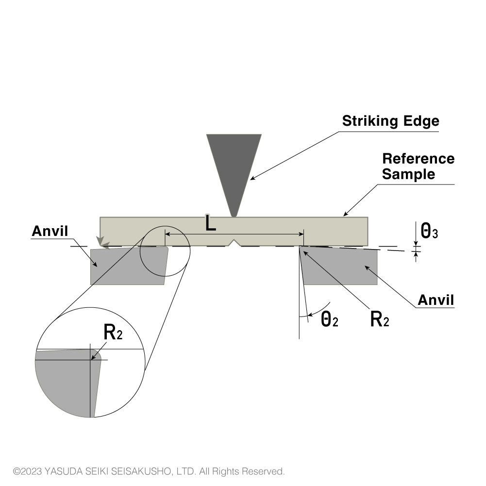
| Symbol | Parameter | ISO/JIS | ASTM |
|---|---|---|---|
| ー | Parallelism between long axis of test sample and reference plane | ±4/1000 | ー |
| R2 | Radius of curvature of anvils | 1±0.1 mm | 3.17±0.12 mm |
| θ2 | Angle of taper of anvils | 10±1 ° | 0 |
| θ3 | Angle of slope of anvils | 5±1 ° | 0 |
| ー | Angle of supports and anvils | 90±0.1 ° | 90° |
| L | Span between sample supports | 62±(0.5/0) mm | 101.6±0.5 mm |
The shape of the anvil differs between ISO (or JIS) and ASTM standards. Therefore, to perform both ISO and ASTM standardized tests, two different anvils shall be prepared.
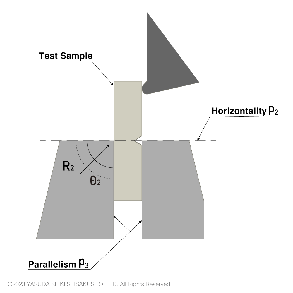
| Symbol | Parameter | ISO/JIS | ASTM |
|---|---|---|---|
| ー | Sample angle | 90±2 ° | ー |
| ー | Parallelism with face of reference sample | ±0.025 mm | ー |
| P2 | Horizontality of top surface of vise | ±3/1000 | ー |
| θ2 | Angle between support block and top surface of vise | 90±0.5 ° | ー |
| P3 | Parallelism in horizontal and vertical direction | ±0.05 mm | ー |
| R2 | Top edge radius of support | 0.2±0.1 mm | 0.25±0.12 mm |
In strict terms the anvil shapes differ between ISO (JIS) and ASTM standards, but are sometimes used mutually as the differences are minor.
Send measured dimensions to the main unit at the press of a button, reducing the time and effort required to input dimensions manually.
*Compatible with No.258-D and No.258-L. Please consult for No.258-PC.
Completely encloses the testing area, ensuring safe operation and preventing sample scatter. Hammer release is controlled via the touchscreen.
Add weights to the hammer to support two capacities.
* Available for model 258-D only.
* An air source of 0.5 MPa and above is required.
Contact Us
For over 70 years, Yasuda Seiki’s testing machines have supported quality control and research & development across various industries, meeting the diverse needs of our clients.